Radiant Floor Layout: A Practical Guide to Planning Your PEX Tubing
Radiant Floor Layout: A Practical Guide to Planning Your PEX Tubing

Getting the radiant floor layout right is the single most important step in any hydronic radiant heating project. You can use the best boiler on the market and the highest-quality PEX tubing available, and still end up with cold spots, uneven temperatures, and pressure imbalances if the layout was poorly planned.
This guide walks through everything that determines a good radiant floor layout: starting with heat loss, choosing the right loop pattern for each room, understanding spacing and loop length rules, and how WBI’s panel systems simplify the process for above-floor installations.
Start with Heat Loss, Not Tube Spacing
Every radiant floor layout begins with a heat loss calculation for each room. This accounts for wall and ceiling insulation, window area and type, air infiltration, and the local design temperature, and tells you the BTU output required per square foot to maintain comfort on the coldest day of the year.
This figure drives everything else. A well-insulated room in a mild climate may need 15 to 20 BTU per square foot. A room with large exterior glazing in a cold climate can need 40 or more. Tube spacing, water temperature, and zone boundaries all follow from it.
Skipping this step is how projects end up with rooms that are chronically too warm or too cold and heat sources that cycle inefficiently.
The Three Main Radiant Floor Layout Patterns

Once you know the heat output required per zone, you can choose the appropriate loop pattern. There are three common approaches, and matching the right pattern to each room produces meaningfully better results than applying a single pattern throughout the entire project.
1. Serpentine
The serpentine pattern runs tubing back and forth in parallel lines across a room, like rows in a field. It is the simplest layout to plan and install, making it a natural choice for rectangular rooms with straightforward geometry. The key characteristic to understand is temperature gradient: the hottest water enters at one end of the loop and the coolest exits at the other.
Over a long loop this creates a noticeable temperature difference across the room. To manage it, always direct the supply side toward the exterior wall or area of greatest heat loss, so the warmest water compensates for where the room loses heat fastest.
2. Counterflow (Reverse Return)
The counterflow pattern interleaves the supply and return runs so that hot and cool water travel side by side throughout the room. At any point across the floor, you have one supply run and one return run adjacent to each other, producing an average temperature that is approximately equal everywhere. This gives noticeably more even floor surface temperatures than serpentine.
It is the preferred pattern for interior rooms without significant exterior walls, large open-plan spaces, and anywhere bare-foot comfort is a priority.
3. Spiral (Snail)
The spiral pattern works outward from the center of a room or inward from the perimeter, with supply and return runs spiraling alongside each other. Like counterflow, it produces even distribution because hot and cool water are always adjacent. It is best suited to square or near-square rooms and is often used in high-performance slab installations where thermal uniformity is the priority.
Tube Spacing: The Key Numbers to Know
![installedtube-1[1]](https://wbiwarm.com/wp-content/uploads/2024/11/installedtube-11.jpg)
Tube spacing is the center-to-center distance between adjacent tubing runs, and it directly controls how much heat output the floor can deliver. Standard residential spacing runs between 6 and 12 inches on center.
Closer spacing delivers more heat output and more even surface temperatures but uses more tubing. Wider spacing reduces cost and installation time but, without a heat transfer layer, can produce perceptible warm and cool stripes on the floor surface.
6-inch spacing: High heat loss areas, rooms with significant exterior glazing, and floors with higher-resistance coverings like thick tile or carpet.
9-inch spacing: The balanced choice for most living spaces in typical North American climates with standard insulation levels.
12-inch spacing: Well-insulated new construction with low heat loss, polished concrete, or thin stone tile. Standard spacing for WBI’s Ecowarm RadiantBoard panels.
In any installation without an aluminum heat transfer layer, the floor surface between tube runs is cooler than directly above the tubing, and this striping worsens as spacing increases.
WBI’s panel systems address this directly. The aluminum laminate in RadiantBoard and ThermalBoard conducts heat laterally across the full panel surface from each tube run, producing consistent floor temperatures across the entire surface even at 12-inch spacing.
Loop Length and Why It Matters
For half-inch PEX, the standard maximum loop length is 250 to 300 feet. Beyond that, pressure drop increases enough to make flow uneven and the temperature difference between the start and end of the loop large enough to produce noticeable surface variation. Keep all loops within the same zone within roughly 20 to 30 feet of each other, large length disparities make manifold balancing difficult.
Always add 10 to 20 feet per loop for the home run between the manifold and the start of the heated area. If the manifold sits some distance from the zones, this addition can be significant and must be factored into the layout plan before tubing is cut, not after.
Manifold Placement and Zone Planning

The manifold is the central distribution point for the system, where supply and return connections for every loop meet. Place it as close to the center of the zones it serves as the floor plan allows.
In a multi-story home, a manifold on each floor beats a single basement manifold serving everything. Utility rooms and mechanical closets are suitable locations. Avoid manifolds that are difficult to access, exposed to freezing, or so far from the heating zones that home runs consume most of the allowable loop length.
How WBI’s Panel Systems Simplify Radiant Floor Layout
Above-floor panel systems like WBI’s Ecowarm RadiantBoard and ThermalBoard simplify radiant floor layout planning considerably. The tubing routes are pre-cut into the panels at fixed spacing, so the layout geometry is built into the product.
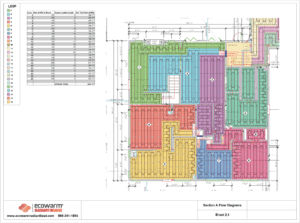
Every project receives a WBI-generated CAD layout with room-by-room floor plans showing exactly which panel type goes where and how the loops connect, eliminating the most common field errors: inconsistent spacing, loops cut too long, and home runs left out of the length calculation.
The aluminum laminate in both RadiantBoard and ThermalBoard also reduces performance sensitivity to exact tube spacing. Because it spreads heat laterally across the full panel surface, the system delivers even floor temperatures at wider spacing than is achievable in a concrete or plywood-only installation.
For concrete and basement applications, WBI’s InsulHeat and RadiantBoard EPS systems combine insulation, vapor barrier, and PEX routing into a single product, streamlining what would otherwise be multiple separate installation steps.
Key Takeaways
- Start with a heat loss calculation for every room. Tube spacing, water temperature, and zone boundaries all follow from it. Skipping this step is the root cause of most radiant performance problems.
- Match the loop pattern to the room: serpentine with supply toward the exterior wall for rooms with significant heat loss on one side; counterflow for interior rooms and open-plan spaces; spiral for square rooms in high-performance slab installations.
- Keep half-inch PEX loops between 150 and 300 feet. Keep loops within the same zone within 20 to 30 feet of each other. Always account for 10 to 20 feet of home run per loop before cutting tubing.
- Use 6-inch spacing in high heat loss areas, 9-inch for typical living spaces, and 12-inch for well-insulated new construction. WBI’s aluminum-laminated panels deliver even surface temperatures at 12-inch spacing that plywood or concrete-only installations cannot match.
- Place manifolds centrally within the zones they serve. Short home runs reduce pressure drop, simplify balancing, and make the system easier to maintain over its 30 to 50 year service life.
- WBI’s Ecowarm RadiantBoard and ThermalBoard systems include project-specific CAD layouts that eliminate guesswork, ensure accurate loop lengths, and remove the most common field installation errors.